

Valve Type:
HLPSL 3C1C/220-3
-32 L 80/80 /EA
-32 H 80/80 /EA
-32 H 80/80 /EA
-32 H 80/80 /EA
-32 H 80/80 /EA
-E4-G24-MA-10M-WMCLS
Technical description
HLPSL - used for Fixed volume pump oil supply system with flow control (open loop)
3 - Threaded Connection of port P and port R of the connection block (according to 6 / 45 ISO Standard 288/1) - G 1/2 BSPP;
C-Additional component:C, standard type;
1 - with a three-way pressure reducing valve, it is used to supply control oil (control pressure should be about 20 bar);
C-2/2-way magnetic ball valve for system unloading: C, without magnetic ball valve;
3 – size 3;
220- the main satey pressure 220bar;
5EA- total 5 spool valve sections with coil;
2-A and B prot (according to 6 / 45 ISO Standard 288/1) - G 1/2 BSPP;
L,H: As bellow image;
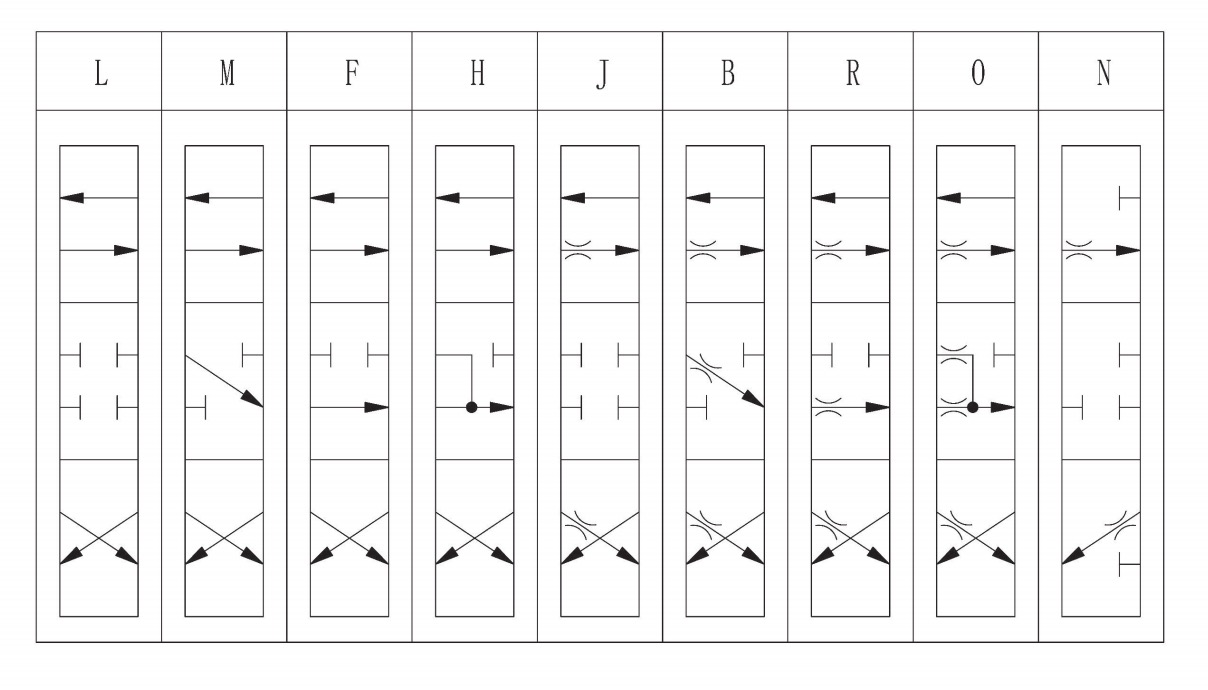
80/80- A and B prot max flow 80 LPM;
G24- 24VDC,DIN 43650
10M- with cable 10m;
MA-anti-explosion type. Grade I,Ex mb I Mb;
WMCL – Supplier's marking that the product is only for export.
1,General:
HLPSL and HLPSV load-sensing proportional directional spool valves are mainly used in engineering machinery to control hydraulic cylinders or hydraulic motors. It is adaptable to manual; electric; hydraulic and pneumatic actuations to achieve step-less speed regulation, without effect of load change. Load-sensing characteristics can make multiple actuators work at different speed and pressure at the same time and independently till the maximum pump flow is reached.
HLPSL valve is designed for constant displacement pump system while HLPSV valve is designed for variable displacement pump system.
Load-sensing proportional directional spool valve is a combined type valve. Generally, it consists of connection Block, Directional Valve and End Plate. If necessary, ancillary blocks can be added on directional valves. Intermediate block could be added between directional valves.
|
References |
size 2 |
size 3 |
size 5 |
|
|
Number of Directional Valve bank |
1~12 |
1~12 |
1~10 |
|
|
Port access type |
thread connection |
thread connection |
thread connection |
|
|
Flow code |
3,6,10,16,25,40 |
3,6,10,16,25,40,63,80 |
16,25,40,63,80,120,160 |
|
|
Max.flow(L/min) |
54 |
100 |
210 |
|
|
Max.pressure(bar) |
420 |
420 |
420 |
|
|
Control Method |
Pilot circuit pressure(bar) |
20~40 |
20~40 |
20~40 |
|
Manual force(N) |
≥2.3Nm |
≥1.3Nm |
≥3Nm |
|
|
Working Pressure(℃) |
-40~80 |
-40~80 |
-40~80 |
|
|
Weight |
Connection Block (kg) |
1.7 |
4 |
8 |
|
Directional Valve bank (kg) |
1.9 |
4 |
8 |
|
|
End Plate (kg) |
0.5 |
1.5 |
2.5 |
|
|
Fix mode |
thread connection M8 |
thread connection M8 |
thread connection M10 |
|
3, Model code
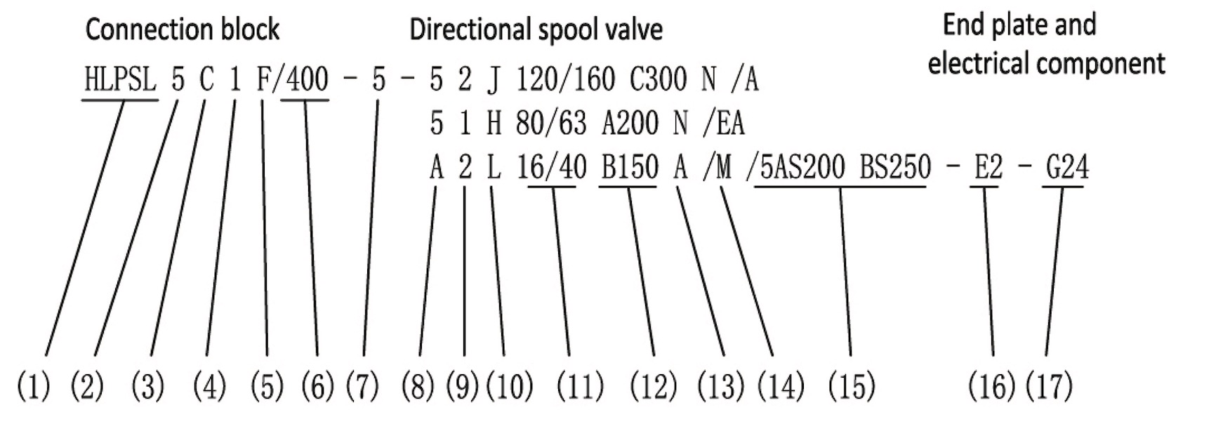
(1)Basic code of connection block
HLPSL: constant displacement pump;HLPSV: variable displacement pump;
(2) Port P & R of the connection block: 2-G3/8; 3- G1/2;4- G3/4;5, 55-G1;6- G1 1/4;
(3) Additional component:C, standard type;G,throttle valve (only used for HLPSL);H,fixed differential overflow valve for improving the circulating pressure (about 14bar, HLPSL);
(4)Pilot oil circuit pressure: 0 without pressure reducing valve; 1 with pressure reducing valve (20 bar); 2 with pressure reducing valve (40 bar);
(5)2/2-way magnetic ball valve for system unloading: C, without magnetic ball valve; F, normally open magnetic ball valve, in case of power supply, the pump is pressurized; in case of power failure, the pump carries out unloading; D: normally closed magnetic ball valve, in case of power supply, the pump carries out unloading; in case of power failure, the pump is pressurized; D../F. . , with pressure limiting valve, it can serve as secondary pressure (F50) with pressure value indicated;
(6)tool adjustable, pressure limiting valve in the connection block: Pressure limiting valve sets such as 63, 120, 210, 280, 315, 350, 400 bar; /NF: without pressure limiting valve (only for HLPSV);
(7)Product series:-2 series; -3 3series; -5 5series;
(8)Thread size of directional spool valve ports A & B: 2-G3/8;3-G1/2; 4-G3/4; 5–G1; A, ancillary block or intermediate transition block ZPL 5S(V)/H hydraulic control shut-off valve;
(9)Directional valve block inflow controller: 1, without inflow controller; 2, standard inflow controller; 4, 3-way flow controllers for inlet and outlet (applicable to N 3/3-way valve); 5, strengthened inflow controller; 8, pre-selectable;
(10) Function symbol of valve core: L, M, F, H, J, B, R, O, N;
(11) Output flow code of ports A & B: Maximum output flow of ports A & B (generally select 3, 6, 10, 16, 25, 40, 63, 80,120,160,210 (L/min);
(12) Secondary pressure limitation: N, without pressure limiting protection; C, limit the pressure of actuator ports A & B at the same time; A---B---, limit the pressure of actuator ports A & B respectively, unit (bar);
(13) Function ON/OFF and pressure outlet: N without function ON/OFF and pressure outlet; X C type pressure limitation; S/S1 AB type pressure limitation; A electrical ON/OFF on side A; B electrical ON/OFF on side B;
(14) Operation manner: A(1,2), manual operation with long handle (1=without handle, 2=with short handle); E, electric proportional control; EA(1,2), electric proportional control and manual operation (1=without handle, 2=with short handle); D, electric switching value control; DA(1,2), electric switching value control and manual operation (1=without handle, 2=with short handle); M, manual friction positioning with long handle; H, pure hydraulic control (two pilot oil ports are in the same direction with oil ports A and B); F, pure hydraulic control (two pilot oil ports are perpendicular to oil ports A and B and outward respectively);
(15) Ancillary block: /2 Ancillary block port size G3/8; /3 Ancillary block port size G1/2; /4 Ancillary block port size G3/4; /5 Ancillary block port size G1;
(16) End plate: E1, standard end plate, external discharge of pilot oil, connecting oil return control port T externally; E2, similar to E1, external discharge of pilot oil, port Y is attached additionally; E3, external discharge of pilot oil, a 2-position 3-way magnetic ball valve is mounted; in case of power supply, the system pressure rises to the pressure of safety valve; E4, similar to E1, internal discharge of pilot oil, port T can be sealed; E5: similar to E2, internal discharge of pilot oil, port T can be sealed; E6, similar to E3, internal discharge of pilot oil, port T can be sealed;
(17) Control voltage and the length of anti-explosion type cable: G12-12VDC;
G24-24VDC;G24Ex-3m-24VDC;G12Ex-3m-12VDC;G24MA-3m-24VDC;G12MA-3m-12VDC(anti-explosion type, length of guide line: 3m, 5m, 10m, etc.)
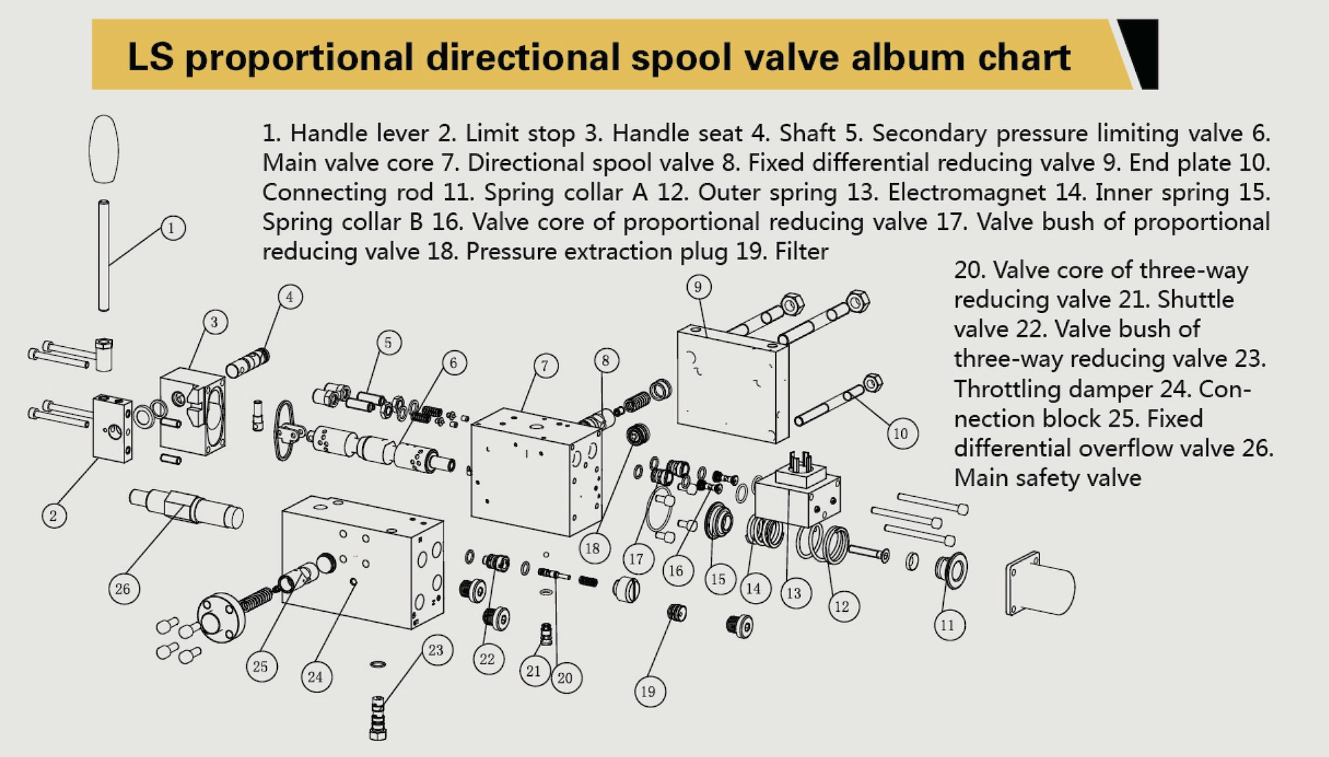
4, Valve parts drawing
5, Valves Reference--have been used from client
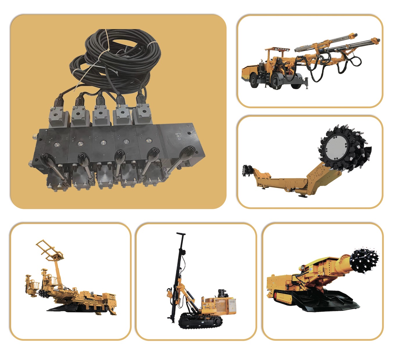
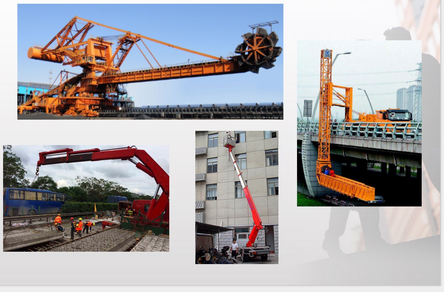
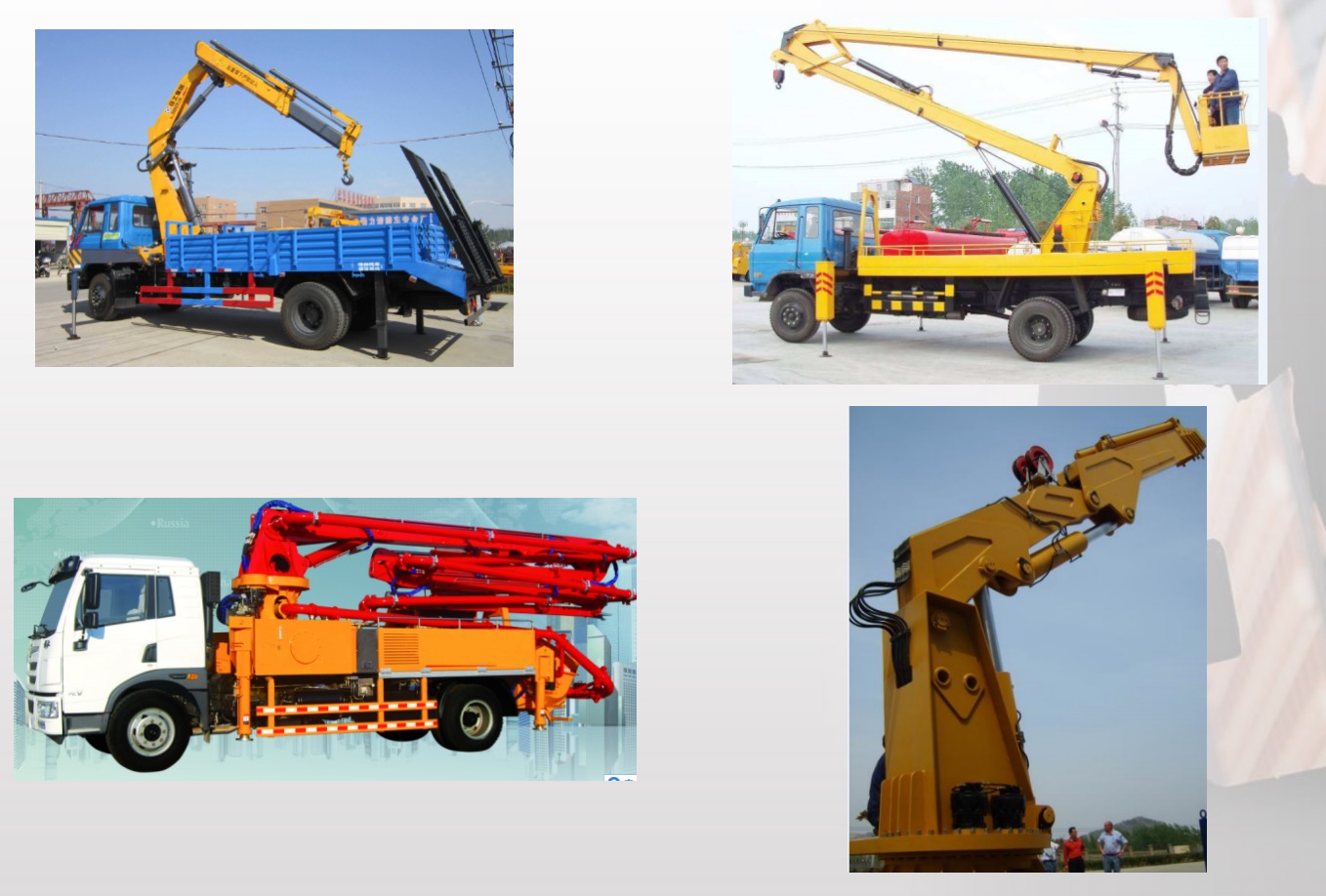
5, Valves view
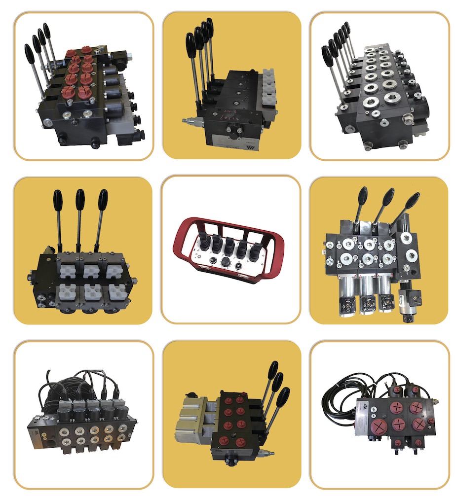
keywood: Psl Hydraulic Proportional Directional Control Valve,Hawe Valve Spools,Hawe Hydraulic Spool,Proportional Directional Control Valve.
If you are interested in the product, contact 2bvideo.com for more information for more information
The information of 2bvideo.com limited shown above is provided by the user or collected on the network. Video 2B does not guarantee the authenticity,accuracy and legitimacy of 2bvideo.com limited information. Video 2B does not involve legal relationships and disputes between users arising from transactions other than secured transactions on this website. Disputes shall be settled by you through negotiation. If you are the person in charge or relevant employee of this enterprise, if you find that the enterprise information is incorrect or want to manage thiscompany, please contact us jacklee1558@gmail.com, after you claim the enterprise, you can obtain management permission, publish supplyand demand information, bring consulting orders, and remove page advertisements.
Main Product:
HL-PSL&PSV Valve,
Proportional Directional Valves,
Load sensing Proportional Valve,
HAWE Type Valve,
Load sensing Loader valve,
Load sensing Hydraulic Valve